Idler Gear
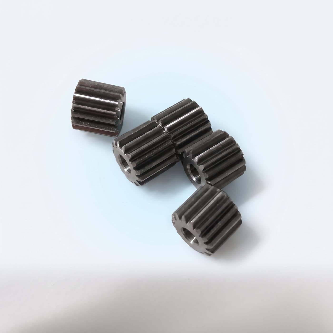
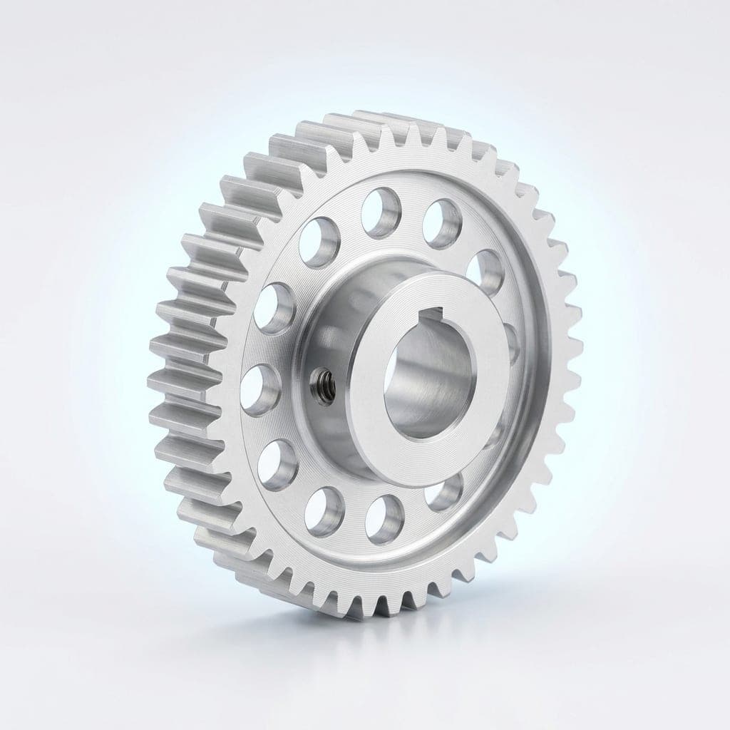
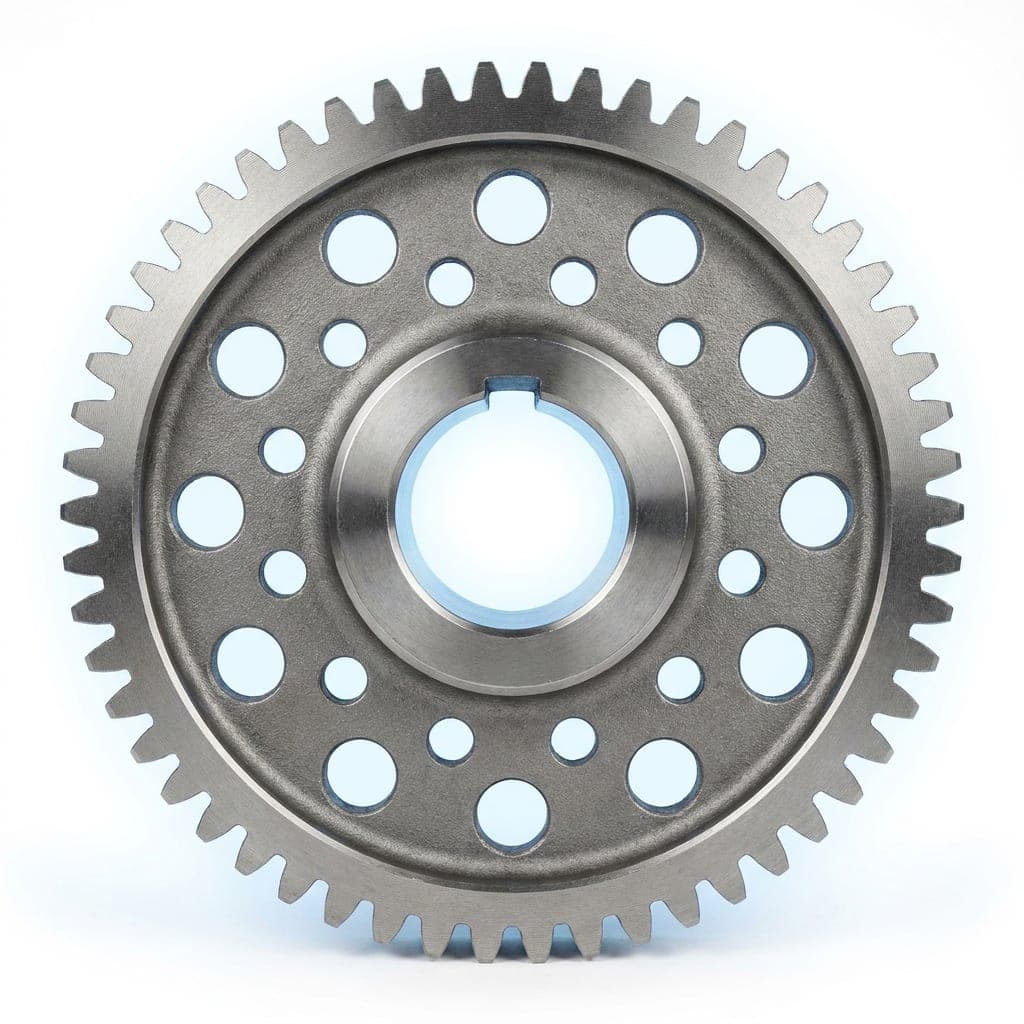
An idler gear sits between the driving and driven gears in a gear train. It does not change the ratio; instead it reverses or corrects the direction of rotation, bridges the distance between shafts and helps spread the load. Sango CNC has manufactured custom idler gears in China for over 15 years for robots, gearboxes, automation equipment and drones.
The range covers diameters from 3 mm to 300 mm and modules from 0.3 to 5.0, in alloy steel, aluminum and engineering plastics. Every gear can be supplied to your drawing or designed by our engineers from your working conditions, with a minimum order of just 5 pieces.
How the Idler Gear Works
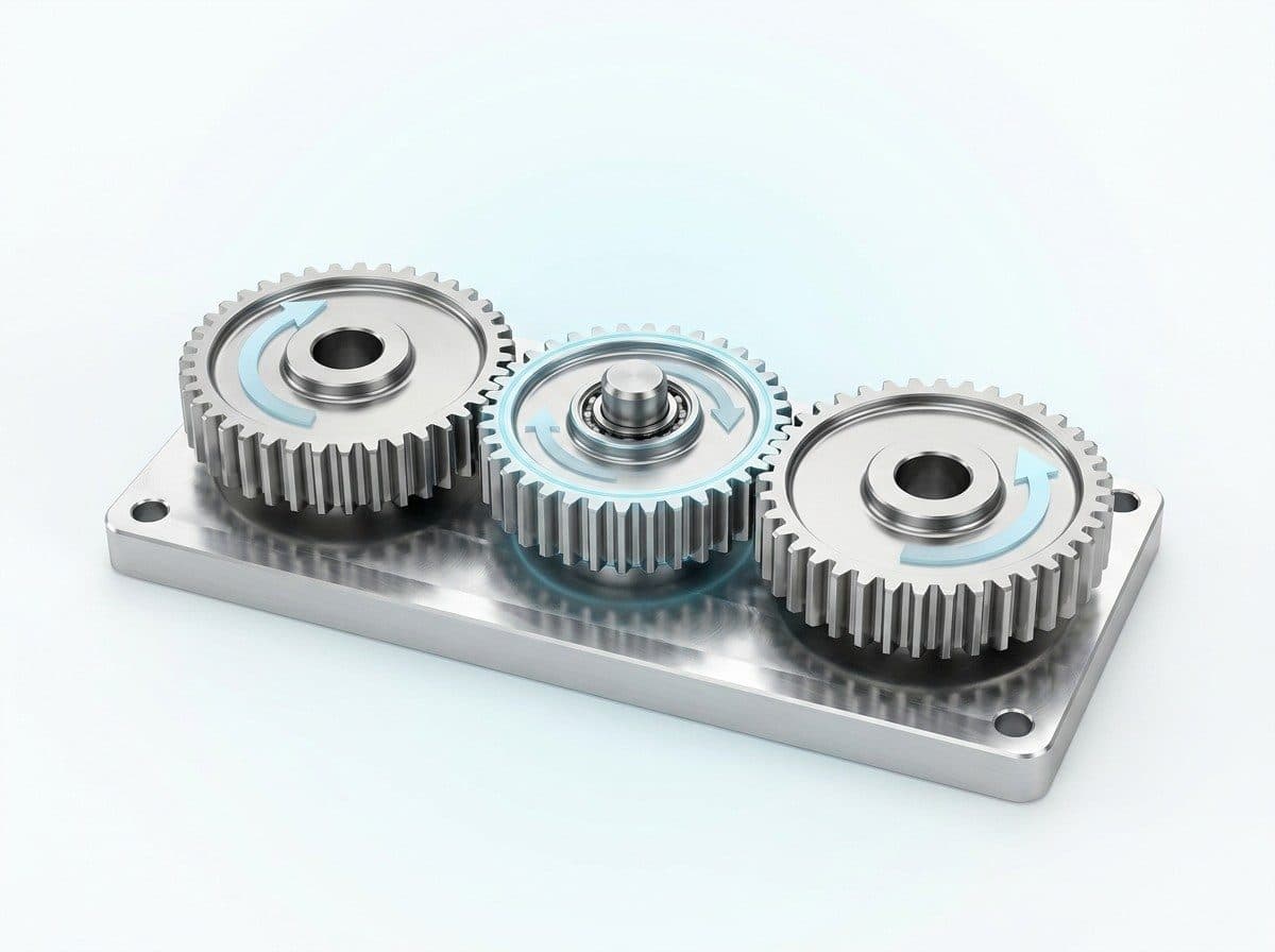
When two gears mesh directly, they turn in opposite directions. Placing an idler gear between them makes the driven gear turn in the same direction as the driver. Because the idler has no effect on the final ratio, the designer can change direction or shaft spacing without recalculating speed or torque.
The idler also closes the gap between shafts that are too far apart to mesh directly. Its position can be adjusted to take up backlash caused by manufacturing tolerances or wear, which reduces shock, vibration and noise during transmission. This makes it valuable in robot arms, precision reducers and measuring instruments.
In more complex gear trains, adding an idler lets torque and load be shared across more teeth. Each tooth carries less stress, wear on individual gears drops and the whole drive lasts longer.
Key Specifications
Why Machine Builders Specify It
Six reasons engineers add an idler to a gear train instead of redesigning the layout.
Changes Direction of Rotation
Makes the driven gear turn the same way as the driver without changing the gear ratio.
Adjustable Engagement Clearance
Idler position can be tuned to remove backlash, cutting vibration and noise in precision drives.
Load Sharing Across More Teeth
Spreads torque over additional teeth, reducing stress on each gear and extending drive life.
Bridges Wide Shaft Spacing
Connects shafts set too far apart to mesh directly, without oversized drive gears.
No Change to Speed or Torque
Ratio stays fixed, so direction or layout can change without recalculating the whole drive.
Built to Your Drawing or Conditions
Supplied from your drawings, or designed by our engineers from your load and working conditions.
Sizes and Technical Ratings
The custom idler gear specifications we support are shown below.
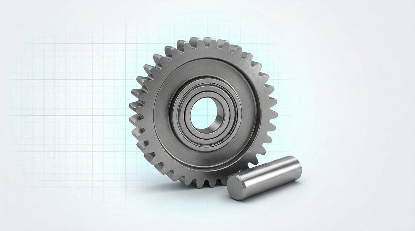
Idler Gear Technical Specifications
Custom idler gears engineered for smooth direction change, low backlash and long service life across automation, automotive and precision equipment.
| Specification Element | Available Options | Selection Criteria |
|---|---|---|
| Material | Alloy steel (e.g. chrome-molybdenum steel), aluminum, engineering polymers (POM, nylon) | Selected per application requirements |
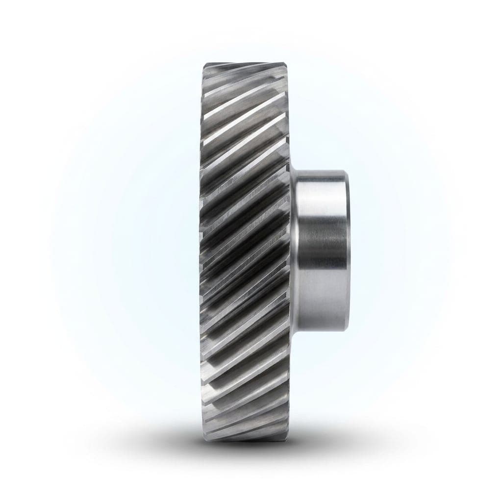
| Diameter & Module | Diameter: 3 mm – 300 mm, Module: 0.3 – 5.0 | Non-standard custom designs supported; common shapes include straight and helical teeth |
| Accuracy & Performance | Up to ISO/DIN/GB Level 5 | Maximum speed of 5,000 RPM (depending on material and design). Carburizing, nitriding, etc. |
Six mounting orientations
The same frame can be bolted base-down, wall mounted or inverted, and the motor can sit above, behind or in line. Quote the code with your order so the unit ships with the oil level and breather set for that orientation.
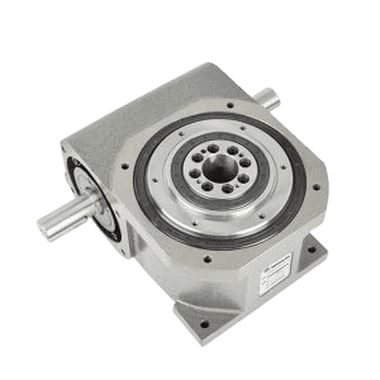
Base down, output up
Standard dial-table orientation.
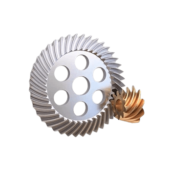
Base down, output side
Right-angle output for wheel drives.
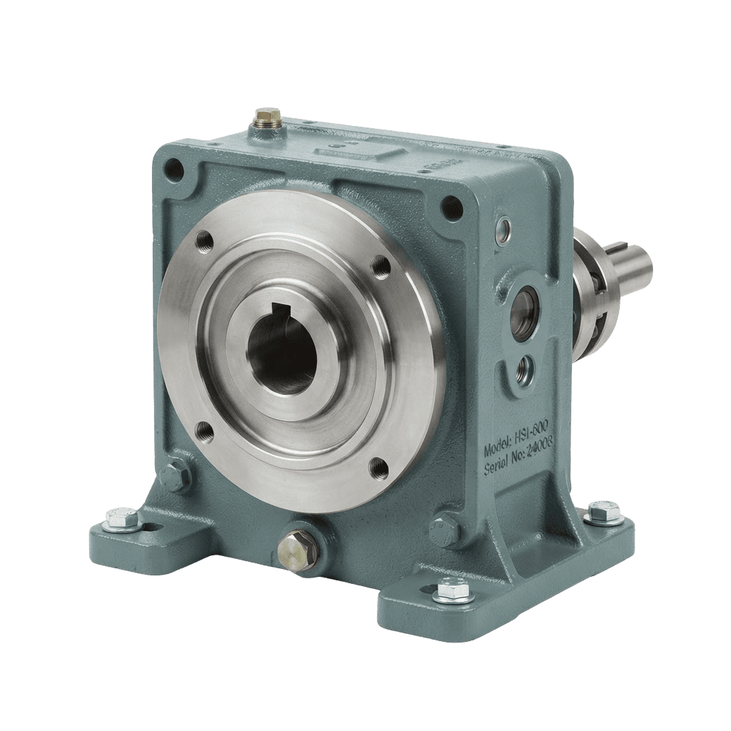
Wall mount, output horizontal
Saves floor space on narrow frames.
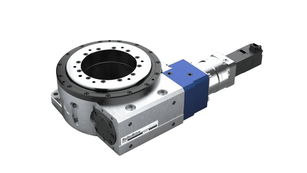
Inverted, output down
Overhead carrier and gantry work.
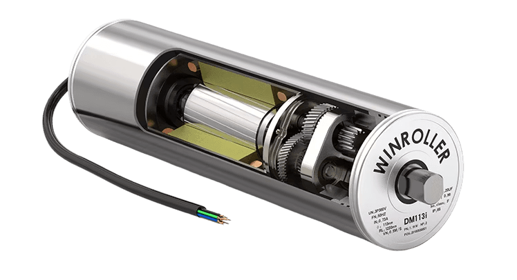
Motor top-mounted
Gearmotor stacked over the housing.
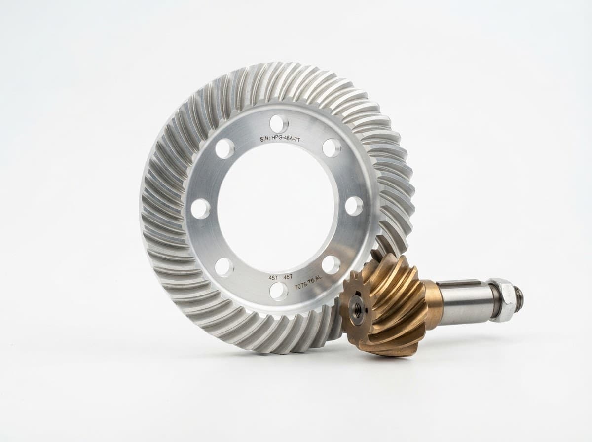
Motor rear-mounted
In-line drive for shallow installations.
Production & Service Procedure
Every idler gear follows the same controlled process, from drawing review to delivery, so each batch meets your requirements.
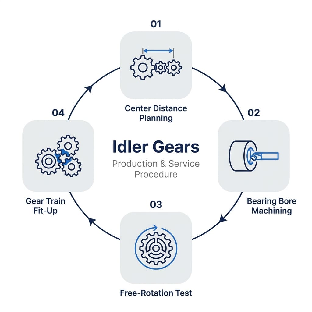
Production Steps
Design and Material Selection
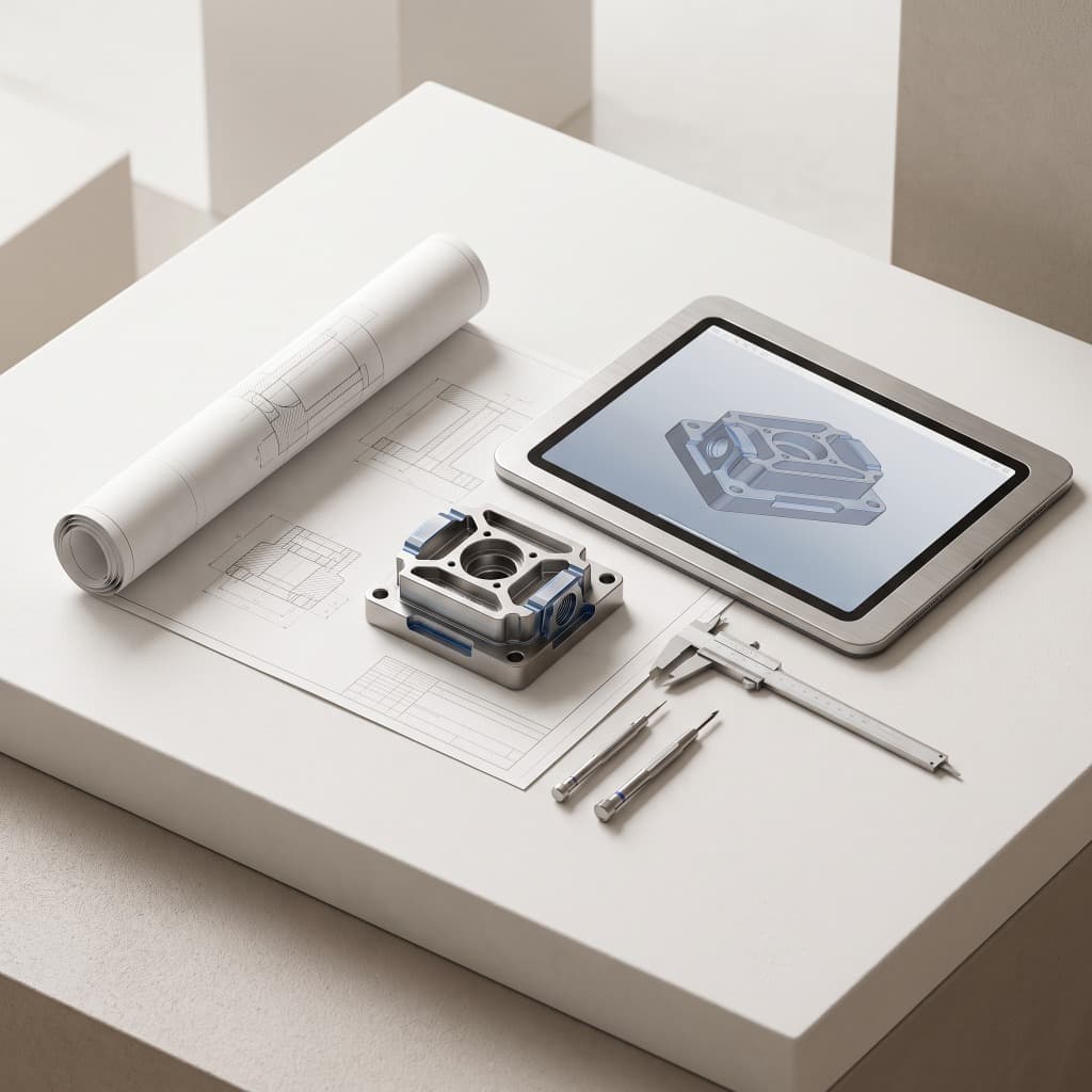
We analyze your drawing with CAD modeling and CAE tooth profile optimization. If you only share working conditions, our engineers design it for you and select the right alloy steel, aluminum or polymer.
Precision Machining
Blanks are turned on CNC lathes, then teeth are cut on gear skiving machines (such as Kashifuji) and CNC gear hobbing machines (such as Ningjiang).
Heat Treatment
Metal gears are carburized, quenched or nitrided to raise surface hardness and wear resistance.
Finishing and Surface Treatment
Fine grinding of bore holes and end faces restores precision after heat treatment, followed by nickel plating, blackening or phosphating as required.
Inspection, Packing and Delivery
CMMs, gear inspection machines and roughness meters check every key dimension, up to ISO Level 5. Gears are cleaned, rust-protected, individually packed and shipped by express, air or sea.
Industries That Use Idler Gears
Idler gears are found wherever a drive needs to change direction, span a distance between shafts or run with minimal backlash. In automation and robotics they are used in robot joints, precision reducers and conveyor belt systems. The automotive industry relies on them in gearboxes, timing systems and starter motors. In drones and aerospace they appear in UAV propulsion systems, model aircraft and aircraft actuation systems. Consumer electronics such as printers, copiers and scanners use small plastic idlers for quiet paper feed, while medical devices including diagnostic instruments, infusion pumps and surgical robots depend on them for smooth, precise motion. Tell us your application, and we will recommend the right material, tooth form and accuracy class.

Popular Products
Engineered for maximum reliability and continuous 24/7 industrial production
Frequently Asked Questions.
Everything you need to know about our idler gears, materials, quality control and custom options.